ALS Storage Ring Parameters
1. General Parameters
| Parameter | Value |
|---|---|
| Beam particle | electron |
| Beam energy | 1.0-1.9 GeV |
| Injection energy | 1.0-1.5 GeV |
| Beam current | 400 mA in multibunch mode 2 x 30 mA in two-bunch mode |
| Filling pattern (multibunch mode) | 276-320 bunches |
| Bunch spacing: multibunch mode |
2 ns |
| Bunch spacing: two-bunch mode |
328 ns |
| Circumference | 196.8 m |
| Number of straight sections | 12 |
| Radio frequency | 500 MHz |
| Parameter | Value at 1.5 GeV | Value at 1.9 GeV |
|---|---|---|
| Beam lifetime: multibunch mode |
3.5 hrs at 400 mA | 8 hrs at 400 mA |
| Beam lifetime: two-bunch mode |
not used | 35 min. at 40 mA |
| Horizontal emittance | 4.2 nm-rad | 6.75 nm-rad |
| Vertical emittance | 0.2 nm-rad* | 0.15 nm-rad* |
| Energy spread (DE/E, rms) | 8 x 10⁻⁴ | 1 x 10⁻³ |
*vertical emittance increased to improve Touschek lifetime.
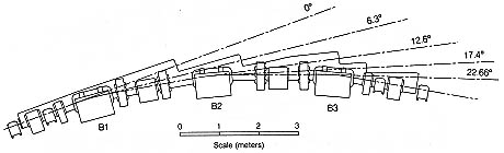
The ALS has 12 straight sections and 12 arc-shaped sections, like the one shown above, containing bend magnets (B), quadrupoles (QFA, QDA, QF, and QD), and sextupoles (SF and SD). Three of the arc sections contain superconducting bend magnets (superbends) and therefore have a modified lattice as shown in the lower image.
2. Horizontal and Vertical Twiss Parameters, Horizontal
Dispersion Functions, Beam Sizes, and Divergences at Photon Source Points*
| Angle and Source** | Axis | a | b | g | Dx | D'x | s (1.5 GeV) | s' (1.5 GeV) | s (1.9 GeV) | s' (1.9 GeV) |
|---|---|---|---|---|---|---|---|---|---|---|
| 0.0 degrees, insertion device | x | 0.0 | 13.6 | 0.075 | 0.06 | 0.0 | 240 | 18 | 310 | 23 |
| 0.0 degrees, insertion device | y | 0.0 | 3.6 | 0.28 | 27 | 7.5 | 23 | 6.5 | ||
| 6.3 degrees, bending magnet | x | -0.03 | 0.35 | 2.8 | 0.03 | 0.09 | 45 | 130 | 57 | 160 |
| 6.3 degrees, bending magnet | y | 6.36 | 19.4 | 2.15 | 62 | 21 | 54 | 18 | ||
| 12.6 degrees, bending magnet | x | 0.39 | 0.9 | 1.3 | 0.07 | -0.05 | 83 | 84 | 100 | 110 |
| 12.6 degrees, bending magnet | y | -0.13 | 1.6 | 0.63 | 18 | 11 | 15 | 9.7 | ||
| 12.6 degrees, superbend magnet | x | 0.035 | 0.95 | 1.05 | 0.057 | -0.04 | 78 | 74 | 98 | 93 |
| 12.6 degrees, superbend magnet | y | 0.04 | 1.50 | 0.68 | 17 | 12 | 15 | 10 | ||
| 17.4 degrees, bending magnet | x | -0.39 | 0.88 | 1.3 | 0.07 | 0.05 | 83 | 84 | 100 | 110 |
| 17.4 degrees, bending magnet | y | 0.13 | 1.6 | 0.63 | 18 | 11 | 15 | 9.7 | ||
| 17.4 degrees, superbend magnet |
x | -0.035 | 0.95 | 1.05 | 0.057 | 0.04 | 78 | 74 | 98 | 93 |
| 17.4 degrees, superbend magnet | y | -0.04 | 1.50 | 0.68 | 17 | 12 | 15 | 10 | ||
| 22.6 degrees, bending magnet | x | 0.34 | 0.39 | 2.8 | 0.04 | -0.12 | 52 | 140 | 65 | 180 |
| 22.6 degrees, bending magnet | y | -7.50 | 18.1 | 3.15 | 60 | 25 | 52 | 22 |
*These are generic lattice functions. There are small
sector-to-sector variations in the parameters for a given source angle
because of the distortion in the lattice functions of the superbends
and the insertion devices. For more precise information, contact Cristoph
Steier (csteier@lbl.gov).
**Angle refers to the direction of the radiation from the source point,
as shown below.